Thursday, May 26, 2016

Two great tips of PCB software CAM350

CAM350 is the industry standard for PCB verification, optimization and output generation to efficiently and effectively drive PCB fabrication.
More and more complicated PCB designs require comprehensive verification before they are transferred to the PCB manufacturer to ensure a perfect and timely produce of bare PCB boards. Problems emerging during the PCB manufacturing can effect the product schedules, result in costly design re-spins, and require modifications to the design that might compromise the PCB design’s intent and integrity . Inspecting, preparing and validating the PCB design before releasing to manufacturing will lead to a vital increasement in efficiency, less risk of design re-spin, and, most importantly, successful electronic products, faster time-to-market, but at less cost.
CAM350 provides a full suite of tools, from design through production, streamlining the transition of PCB design data into right and real PCBs. following are two tips of CAM350 helping the customer to master this great tool.
When the text layer in some PCB Gerber data has a lot of text box,and the distance between text box and PAD can not meet the process capability.When the Gerber data has a large area of copper foil cover, the distance between lines or PAD and copper is beyond to the production requirements, and the outline size is big…You can draw on the experience of treatment methods of this article.
One,When the Gerber data has a large area of copper foil cover, the distance between lines or PAD and copper is beyond to the production requirements, and the outline size is big,you can use the below method to rapidly trimming the distance between lines or PAD and copper.
1, Copy all the PAD in the circuit layer( this is the first layer) into an empty layer.Delete the corresponding PAD on the copper sheet and enlarge the rest PAD as a reduction of the line layer(that is second layer).
2, then copy the first layer into an empty layer.Delete the copper sheet as third layer.Combination way is: the first layer , the second layer , the third layer.
In general, in order to reduce the amount of data, we can keep only copper sheet the first layer .If only the distance between welding to copper sheet is not enough,you can copy the welding layer that is enlarged and can meet the process capability into an empty layer.Delete the correspongding sold mask on copper sheet, and enlarge the rest sold mask as second layer.
Note: after using this method to completes the circuit, be sure to use the order: Utilities–>Convert Composite to convert multiple layers into composite,and change this composite to one layer.And then use the order:Anglysis–>Compare Layers to check this layer with original layer carefully .
Two, when the text layer in some Gerber data has a lot of text box,and the distance between text box and PAD can not meet the process capability,you can draw on the experience of below methods :
1, Use the order:Edit–>Move Vtx/Seg to stretch the text box up to specifications,and then make it flash.

2, then make the other text box of the same type the same flash.But note that after making it Flash ,the flash must be broken up, in case of rotation of D date when openning the data next time.
Source from http://www.ifastpcb.com/blog/two-great-tips-pcb-software-cam350/

Little PCB knowledge – the relation between ounces and thickness of bonded copper

Today we going to share the pcb knowledge about the copper thickness unit, which should be usefull for the new PCB designers.
The thickness of 1 oz is about 35 um.
1 oz mean weight of the average copper foil in the area of 1 square foot is 28.35g, which use the the weight of unit area to represent the average thickness of copper thinness.
Conversion methods:
1 square foot = 929.0304 square centimeters,
The copper foil weight divided by the density and the surface area,that is the thickness of copper foil!
The density of Cu = 8.9 kg/dm ^ 3
Copper thickness is T
Tx929.0304 square centimeters x8.9 g/cm3 = 1 oz = 28.35 g/cm2,
T = 0.0034287 cm = 34.287 um
The relation between PCB line width and the current
One, the calculation method is as follows:
First calculate the Track sectional area.Most of the copper foil thickness of the PCB is 35 um (if the copper thickness is not sure,you can ask your cooperated PCB manufacturer).The copper thickness multiplied by the line width is the cross-sectional area.Pay attention to the conversion into square millmeter.Experience value in a current density v is 15 ~ 25 amps/mm2.The experience value multiplied by the sectional area is capacity.
I = KT0.44A0.75
K means the correction coefficient.It takes 0.024 when the copper wire is in the inner layer.And it takes 0.048 when the copper wire is in the outer layer.
T means the maximum temperature rise,and the unit is degrees Celsius (copper melting point is 1060 ℃)
A means cross-sectional area of copper, and the unit is square MIL (not mm , pay attention to square MIL.)
I means allowable maximum current, and the unit is the ampere (amp)
Generally, 10 mil = 0.010 inch = 0.254 ,which can be 1 A.250 mil = 6.35 mm, which can be 8.3 A
Two, the data:
The calculation of PCB current-carrying capacity is always lack of authoritative technology method and formula. Experienced CAD engineers rely on personal experience to make more accurate judgment.But for CAD novice, it meets a difficult problem.
PCB current-carrying capacity depends on the following factors:line width, line thickness (copper foil thickness) , the permissible temperature rise.As everybody knows, the wider PCB line is, the greater the current-carrying capacity is.Assuming that under the same conditions, 10 mil line can withstand the 1 A, then how much current can 50 mil line withstand? Is it 5 A?Naturally the answer is “no”.Please see the following data from the international authoritative institutions :
The unit of line width is Inch ( 1 Inch = 25.4 millimetres ) 1 oz copper = 35 microns thickness, 2 oz. = 70 microns thickness, 1 oz = 0.035 mm, 1 mil = 10∧-3 Inch.
In experiments, the length of wire line causes the line resistance that causes the pressure drop,which has to be considered.Tin in the process is just to increase the current capacity,but it is hard to control the volume of the tin.1 OZ copper and 1 mm width, usually 1-3 A . Specifically see your line length and the requirements for the pressure drop.
The maximum current value should mean the maximum allowable value under the temperature limit.Fusing value is the value of copper melting.Eg. 50 mil 1 oz temperature 1060 degrees (i.e. copper melting point), the current is 22.8 A
Safe current of aluminium wire is 4-5 A per square millimeter
Safe current of copper wire is 5-6 A per square millimeter
The copper wire of maximum current can run 10A with one square millimeter.
The relationship between sectional area of wire and the current
Safety calculation method of copper wire is as below:
The safe current-carrying capacity of copper power wire of 2.5 mm² is 28A
The safe current-carrying capacity of copper power wire of 4 mm² is 35A
The safe current-carrying capacity of copper power wire of 6 mm² is 48A
The safe current-carrying capacity of copper power wire of 10 mm² is 65A
The safe current-carrying capacity of copper power wire of 16 mm² is 91A
The safe current-carrying capacity of copper power wire of 25 mm² is 120A
If it is aluminium wire, wire diameter is 1.5 -2 times of copper wire.
If the current of copper wire is less than 28 A, 10A per every square millimeter is safe .
If the current of copper wire is larger than 120A, 5 A per square millimeter is OK.
The current that can normally go through the sectional area of the wire,has a choice according to the sum of needed current.
The aluminum wire below 10 mm², square millimeter number multiplied by five is ok, if the copper wire,rose up a gear
The copper wire of 2.5 square, is calculated at four square. More than one hundred ,they are all cross-sectional area multiplied by 2.
Under 25 square,multiplied by four,
More than 35 square, multiplied by three
70 and 95 square,multiplied by 2.5
Note: it is only as estimation.It is not very accurate.
In addition ,if the copper wire is less than 6 mm² in indoor electronic wire,it is safy that every square current is not more than 10A.From this perspective,you can choose copper wire of 1.5 square or aluminium wire of 2.5 square.
Within 10 meters,the wire current density of 6A is more appropriate.
10 to 50 meters, 3 A/mm²,
50-200 meters, 2 A/mm²,
More than 500 meters, less than 1 A/mm².
From this point of view, if it is not far away, you can choose copper wire of four square or aluminum wire of 6 square.
If that’s the distance of 150 meters of power supply (it is tall buildings or not),copper wire of four square must be adopted .

The impedance of the wire is proportional to its length, and is inversely proportional to the wire diameter.Please use power with special attention to the wire and wire diameter of the input and output wire.In order to prevent the accidents caused by overheat line because of the too big current.

Source from http://www.ifastpcb.com/blog/little-pcb-knowledge-relation-ounces-thickness-bonded-copper/

Tuesday, May 24, 2016

Application of digital ink-jet printing technology in the PCB manufacturing

Use digital link-jet printing technology to develop and produce PCB, which can positively simplify the production process and shorten the production cycle; which greatly reduce the expensive production equipments and save the cost. It greatly reaches the goal of “energy conservation and emissions reduction”, especially for reducing the capacity of waste-water and improving the environmental pollution, move to “green production”. Therefore, “digital ink-jet printing technology” will get rapidly promotion and application in the PCB industry, and will become the mainstream in PCB manufacturing!
Following is the overview of the ink-jet printing technology from three aspects:

1. Application of digital ink-jet printing technology in PCB industry

“Digital ink-jet printing technology” has mainly four aspects of the application in PCB industry:
(1) Using digital ink-jet printing technology to generate the pattern of corrosion or plating resistance. Using this technology can reduce more than 60% production process of traditional “pattern transfer” process,and can save about 60% of the ink and dry film,and can decrease more than 60% of organic wastewater treatment and discharge.
(2) Applying “digital ink-jet printing technology” to form solder mask and legends. Adopting this technique can reduce more than 60% of the production process of traditional solder mask and characters, and can save more than 50% of solder mask ink,and can reduce more than 60% of organic wastewater treatment and discharge,and can improve the product percent of pass and shorten the production cycle, to reduce the cost of solder mask.
(3) Adopting “digital ink-jet printing technology” produce PCB products directly.The flow is: jet printing conductive graphics on the base material——low temperature sintering——jet printing medium layer——jet printing plating through holes——low temperature sintering——jet printing conductive graphics, repeating the processes to form the required “laminated board”.
Of course, the application of “digital ink-jet printing technology”, needs to follow the development rule of all things,from small to large, from weak to strong, from local to overall, from low level to high level.Therefore, it has to be from the first application in “corrosion or plating resistance” and solder mask and legends,and then to the full jet printing technology based pcb products .

2. key equipment and materials

(1) key equipment – “digital-control” inkjet printer. Including: i). the print head, can spray 5 to 50PL of link drops. ii) productivity, can satisfy the PCB mass production requirements. For example, the working time of 20 x24 square inch working in process board should be between 20 to 60 seconds.
(2) the key materials: printing ink.
The ink usd for ink-jet printing is different from the conventional ink ,especially the viscosity and thixotropy.For the conductive ink used in the PCB production which fully adopt “digital ink-jet printing technology”,must be the ink of “nanoscale metal particles (such as silver, gold, copper, etc.)” , to ensure the sintering under the condition of low temperature , and achieve the conductivity of the metal conductor.

3. Current situation

At present, Japan and the United States have market-oriented professional digital ink-jet printing and special printing ink.Such as MJ6151 series products of Japan CicroCraft k.k ,and Greenjet series(digital solder mask printing system) products of American Printar Inc. These products can be applied in the large-scale production of 50-150 um wire and all kinds of graphics. “Super” digital inkjet printer and “nano silver ink” and “nano gold ink” have emerged, that is to say, the ink drop of 3-5 PL can be jet-printed ,and wire of 3-30um can be producted.So manufacturing full printed electronic products is getting there!
Must be fully aware that full printed electronic using ink-jet printing technology is great innovation which simplifies the PCB production processes, and reduce the cost and greatly improve the environment pollution and foward the green manufacturing, and is an revolutionary progress of PCB industry


iFastPCB will keep continuous attention on this technology, and will apply it at right time in the future t.

Vertical Continuous Plating(VCP) line completely defeat traditional plating line to boost the healthy development of PCB manufacturing

With the development of electronic devices toward to diversification of varieties ,functionality and Product minimization, Printed Circuit Board manufacturing industry faces the challenge of more sophisticated equipment and more advanced technologies.
Universe Group ,as professional wet pcb process equipment manufacturer, is facing current challenges and gradually introducing industy 4.0 intelligent production mode. It reserches and developes and make independently the vertical continuous plating line (VCP). Since 2011, just a few short years, VCP sales volume has exceeded 121 lines. It is widely used for pcb manufacturing process such as: panel plating, graphics plating, filling holes or half-filling holes plating, soft board plating and so on.
It is reported, the design concept of the universe group VCP line is updated on the basis of traditional plating line .Compared with traditional plating line, it has more advantages as below :
Device of loading / unloading material: the universe group VCP line adopts automatic design of loading and unloading material. The shortest cycle is only 8 seconds.
While traditional plating line can only load and unload the material by manual, which needs more operators, and the labor intensity is high, the staff turnover is fast, which is easy to cause Labour shortages.
Transmission structure: the universe group VCP line adopts transmission way of combination chain type with movable cathode pylons. Pylons drive more smoothly and connectibity is better. it has the advantage of less impact and low noise, etc;
While traditional plating line, impact and noise of bumble motor making serious noise pollution.
The device of adding copper ball:the VCP line can add copper ball during the PCB production.You can add the copper ball at any time without stopping the machine.This operation is very convenient and the copper ball will not fall into the copper groove .
While traditional plating line needs to stop the machine when adding copper ball, which is extremely unconvenient, and copper ball is easy to fall into the groove. Its efficiency is low and affect the production capacity.
Production environment: in the same capacity, compared with traditional plating ,the contact area between liquid and air of VCP line is smaller,which is only a third of traditional plating line.Using the lateral jet produces less waste gas,so the required pumping air volume is small,and energy consumption is slow.The top extraction design of sealed equipment can greatly reduce gas leaks, which makes work environment safe and comfortable;
While traditional plating line is open.It is difficult for traditional plating line to achieve the effect of VCP in sealing.Because the quantity of copper plating tank is big, and the surface area of exposed liquid in air is much, and pylon has frequent movement which produces a large amonut of waste gas. So the whole workshop has harmful gas,which has serious impact on employee health. The pcb manufacturer need to configure high-power convulsions system to make the environment improve slightly, and energy consumption is high.The conservative estimated enerhy consumption is more than two times than VCP line .
Process control: the copper tank of the universe VCP line is all connected, and uniform circular, whose tank is equivalent to one copper groove.In process control, only liquid in one copper slot or several copper slot is needed,which is simple and easy to analysis;

And traditional plating line, the number of copper slot is much.The copper tank works alone and does not connect together.In process control,the liquid in every copper tank is needed to analysis,which makes process tedious and big workload.
Body material: the body of VCP line is made of flame retardant PVC material of V0 class.When in the fire,it most becomes black ,but not burn,which can effectively prevent the fire.The so-called prevention is like that;
While traditional plating line is generally made of ordinary PP material.PP material is not only easy to burn but more help burn. Throughout the fire in PCB factory, it is mostly caused by plating workshop,while the flammable PP material is one of the main culprit causing the fire;
Floor space:the structrure of the VCP line is compact, and the floor space is small ;The universe group has a total four kinds of VCP equipment:
double up-down VCP line(called a DVCP), single up-down VCP line, circular transfer VCP line, one-piece transmission ring VCP line.They can satisfy users of different site conditions,and it is very flexible and convenient;
While traditional plating line, the floor area is larger, and requirements for plant height is high, which is at least 4 ~ 5 meters;Under the same capacity condition,space required by VCP line is only 50% of the traditional plating line, which greatly save space.
Maintenance: the structure of the VCP line is simple, and adopt humanized design with fool proof, and quick release, and color letter management.It is extremely convenient and high efficiency, and it is also easy to achieve 7S standard.
While traditional plating line ,its copper plating tank span is big, and it is easy to cause accident. It often exists environmental problems, and maintenance person need to be down to clean the copper tank, extremely unconvenient. The fixture needs frequent maintenance and repair, and the cost is high.
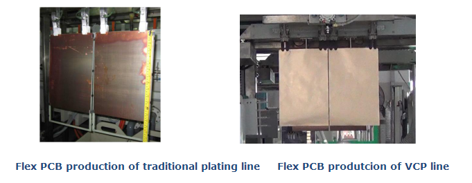
Flexiable PCB production: the VCP line can directly produce the flex PCB board with 0.036 mm thickness or above without the fixed framework; Traditional plating line need the frame during producting any kinds of flex board.
PCB_manufacturing_plating line 7
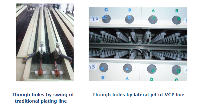
Through-hole ability: the VCP line uses the supercharged nozzle to spray up closely, to strengthen liquid penetration ability, which can meet the demand of HDI PCB production;
While traditional plating line makes the potion into the hole only by soaking and swing. Its strength is small, and penetration ability is limited, so it can only meet the demand of ordinary plate production.
PCB_manufacturing_plating line 8
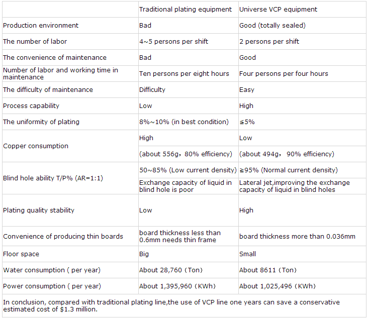
Conclusion: the advantages and disadvantages between VCP line and traditional plating line, as follows:
PCB_manufacturing_plating line 9
Due to the limitations of structure and technology, traditional plating line has gradually lost its competitive advantage.In addition to producing a small part of the high depth of the products,the more cost-effective VCP line will replace the traditional plating line.Universe Group VCP line is a good example of industy.we believe,under the impetus of outstanding enterprise as the universe group, the development or PCB manufacturing industry toward to the sustainable and healthy direction of low consumption, low pollution, high quality, high efficient.


Source from http://www.ifastpcb.com/blog/vertical-continuous-platingvcp-line-completely-defeat-traditional-plating-line-boost-healthy-development-pcb-manufacturing-2/

The introduction of common standards of PCB manufacture and Assembly

Today we are going to introduce some common standards of PCB manufacture and Assembly
1) IPC – ESD – 2020: Joint standard of electrostatic discharge controlling program development ,including design, build, implement and maintain of electrostatic discharge control program. According to some experience of the military and commercial organizations, providing guide for processing and protecting of electrostatic discharge in sensitive period.
2) IPC-SA-61A : Post solder semi-aqueous cleaning handbook, including all aspects of Semi-aqueous Cleaning,including chemical and productive residue, equipment, technology, process control and considerations of environment and safety .
3) IPC-AC-62A: post solder aqueous cleaning handbook.Describing PCB manufacturing residue, the types and properties of aqueous cleaner, the process of aqueous cleaning, equipment and processes, quality control, environmental control ,the safety of employees,the test of cleanliness and its cost.
4)IPC-DRM-40E: Through-hole solder evaluation handbook reference.Describing the components,the hole wall,and the welding surface in detail according to the standard requirement.In addition, also including the 3D graphics generated by computer.Covering the filling tin, contact Angle, wetting, vertical filling, welding pad cover and a large number of weld defects.
5) IPC – TA – 722: Solder technology evaluation reference, includes 45 articles of welding technology in all aspects.The content involves ordinary welding ,welding materials, manual welding, batch welding, wave soldering, reflow soldering, gas phase welding and infrared welding.
6) IPC – 7525: template design guidelines.Providing guidelines for the design and manufacture of template for solder paste and surface mount adhesive.Also discussing template design with the application of surface-mount technology.Introducing hybrid technology with through-hole or flip chip components,including the overprint, double seal and phase type template design.
7) IPC/EIA J – STD – 004: requirements for soldering fluxes,contain technical indicators and classification,such as rosin, resin and others.Solding fulxes can be divided into two classes: organic and inorganic flux according to content and activation of halide in fluxes.
8) IPC/EIA J – STD – 005: requirements for soldering pastes,list the characteristics and technical index requirements of solder paste, including test method and the metal content standards, as well as the viscosity, collapse, solder balls, viscosity and wetting properties of solder paste.
9) IPC/EIA J – STD – 006A: requirements for solder alloy of electronic grade,solding fluxes,influx solid solder,provide term name, specification requirements and test methods for electronic grade solder alloy,for flux of bar, strip, and powder, for solding tin of influx, for the application of electronic soldering, for special electronic grade solder .
10) IPC-Ca-821: The general requirements of thermal conductive adhesive.Including requirements and test methods for thermal conductivity of the dielectric that makes the copmonents adhere the suitable location.
11) IPC – 3406: guide of conductive surface coating binder,provides the guide for the secection of conductive adhesive which is as Solder alternatives in the electronic manufacturing.
12) IPC – AJ – 820: handbook of PCB assembly and welding, contains descriptions of assembling and welding inspection technology, including the terms and definitions;printed circuit board, components and pin type, material of welding point, installation, specification reference of design and outline;Welding technology and packaging;Cleaning and labeling;Quality assurance and testing.
13) the IPC – 7530: Temperature curve guide of batch welding process(reflow soldering and wave soldering. In the temperature curve to obtain, using all kinds of test means,technology and methods provides guidance for establishing the best graphics.
14) IPC – TR – 460 – a: Troubleshooting list of printed circuit board wave soldering,for a possible failure caused by wave soldering , recommends correction measures list.
15) IPC/EIA/JEDEC J – STD – 003A: the weldability test of printed circuit boards.
16) the IPC – 7095: design of SGA device and supplement of assembly process,provide all kinds of useful operation imformation for people who are using the SGA device or have the consideration to the grid array;and also provide guidance for testing and servicing of SGA and provide reliable information about the field of SGA.
17) IPC – M – I08: the instruction manual of cleaning,includes the IPC cleaning instruction of the latest version,and provide help for engineers when they decided to product cleaning process and troubleshoot.
18) IPC – CH – 65 – A: the washing instructions of printed circuit board assembly,provide the reference for the current and new cleaning method in the electronics industry, including descriptions and discuss of all kinds of cleaning methods.This washing instructions explain the relationship among various materials, process and the pollutant during the operation of manufacturing and assembly.
19) IPC – SC – 60 A:cleaning manual of solvent after welding,provides the use of solvent cleaning technology in automatic welding and manual welding,and discuss the nature of the solvent and the residue and process control, and environmental issues.In automatic welding and manual welding is given in the use of solvent cleaning technology, discusses the nature of the solvent, the residue and process control, and environmental issues.
20) IPC – 9201: the manual of surface insulation resistance,includes the terms, the theory, test process and test means of surface insulation resistance(SIR),and also includes temperature, humidity (TH) test, failure mode and troubleshooting.
21) IPC – DRM – 53: electronics assembly desktop reference manual,is used to indicate diagrams and photographs of through-hole installation and SMT assembly technology.
22) IPC – M – 103: SMT assembly manual, includes all 21 IPC files of SMT.
23) IPC – M – I04: printed circuit board assembly manual,contains ten of the most widely used files about the printed circuit board assembly
24) IPC – CC – 830 B: performance and appraisal of electronic insulation compounds in
printed circuit board assembly. An industrial standard that meet quality and qualification of conformal coating .
25) IPC – S – 816: surface-mount technology guide and checklist.This troubleshooting guide lists all types of process problems and their solutions of the SMT assembly , including bridge, leakage welding, component placement arrangement, etc.
26) IPC – CM – 770 D: components installation guide of printed circuit board,provides effective guidance for components in printed circuit board assembly,and reviews the relevant standards, the influence and distribution situation,including assembly technology (including manual and automatic and surface-mount technology and flip chip assembly technology) and considering the follow-up welding, cleaning and laminating process.
27) IPC – 7129: calculation of defects per million opportunities(DPMO) and printed circuit board assembly manufacturing index.A benchmark that is agreed by calculating defect and quality-related industrial sectors.It provides a satisfactory way for calculation of defects per million opportunities(DPMO).
28) IPC – 9261 : production estimation of printed circuit board assembly and failure per million opportunities in he assembly.It defines the reliable method of calculation the number of failure per million opportunities in printed circuit board assembly.It is evaluation criteria of each stage in process of assembly.
29) IPC – D – 279: design guidelines of reliable surface-mount technology and printed circuit board assembly .The guidlines are for manufacturing process of the reliability in PCB of surface-mount technology and blending technology ,including the design idea.
30) IPC – 2546: the combination requirement passed in the points in printed circuit board assembly.Describing the material movement system, such as actuators and buffers, manual replacement, automatic silk screen printing, automatic distribution of adhesive, automatic SMT placement, automatic placement of plated through hole, forced convection, and infrared reflow oven and wave soldering.
31) IPC – PE – 740 A: troubleshooting of PCB manufacturing and assembly .Including case histories and calibration activities of problems that appear in the process of the design, manufacture, assembly and testing.
32) IPC – 6010: printed circuit board quality standards and performance specifications series manual. Including quality standards and performance standards formulated by the American association of printed circuit board for all printed circuit board.
33) IPC – 6018 A: microwave end product printed circuit board inspection and test


34) IPC – D – 317 A: design guidelines for electronic packaging utilizing high speed techniques.To guide the design of high-speed circuits, including the mechanical and electrical considerations and performance testing.

Source from: http://www.ifastpcb.com/blog/introduction-common-standard-pcb-manufacture-assembly/